Contents
- 1 What is the clutch and types of clutches?
- 1.1 Types of Clutches
- 1.2 Single Plate Clutch
- 1.3 Working
- 1.4 Multi-Plate Clutch
- 1.5 Cone Clutch
- 1.6 Centrifugal Clutch
- 1.7 Working
- 1.8 Semi-Centrifugal Clutch
- 1.9 Construction of Semi-Centrifugal Clutch
- 1.10 Diaphragm Clutch
- 1.11 Advantages
- 1.12 Dog and Spline Clutch
- 1.13 Electromagnetic Clutch
- 1.14 Vacuum Clutch
- 1.15 Working and Construction
- 1.16 Hydraulic Clutch
- 1.17 Freewheel Unit
- 1.18 Working of the Freewheel
What is the clutch and types of clutches?
In this article, we are going to explain what is clutch, different types of the clutch, and how they work with diagrams.
First, let’s understand what is a clutch?
A Clutch is a mechanical device that engages or disengages with the power transmission from the driving shaft to drive shaft.
In the mechanism, one shaft is connected to the engine or another power unit (driving member) and other shafts (driven member) provide output power.
Clutches that are used in a motor vehicles have similar construction and operation. The different types of clutch have differences in linkage and pressure plate assemblies.
Some types of clutch are used for heavy-duty applications with having two friction plates and an intermediate pressure plate. There are also some types of the clutch which are hydraulically operated. The dry single-plate type of friction clutch is widely used in USA passenger cars.
There are various types of clutches are used in automobile and it is depending on the type and use of the friction.
Most of the design of clutches uses a number of coil springs but some are exceptional uses diaphragm or conical springs. There is also a type of friction material varies in clutches of various passenger cars.
Now let’s see Different
Types of Clutches
Below is different types of clutch used in the automobile industry.
1. Friction Clutch
- Single Plate Clutch
- Multiplate Clutch
- Wet
- Dry
- Cone Clutch
- External
- Internal
- Centrifugal Clutch
- Semi-centrifugal Clutch
- Conical Spring Clutch or Diaphragm Clutch
- Tapered Finger Type
- Crown Spring Type
- Positive Clutch
- Dog Clutch
- Spline Clutch
- Hydraulic Clutch
- Electromagnetic Clutch
- Vacuum Clutch
- Overrunning Clutch or Freewheel Unit
Single Plate Clutch
The single plate clutches are widely used type of clutch in most of the modern light vehicles. The Clutch is transmitted torque from the engine to the transmission input shaft. As per the name it has only one clutch plate.
The single-plate clutch has a clutch plate, friction plate, pressure plate, flywheel, bearings, clutch spring, and nut-bolts.
A single plate clutch has only one plate and it is attached to splines of the clutch plate. The single-plate clutch is of the main components of the clutch. This clutch plate is a thin metallic disc having both side friction surfaces.
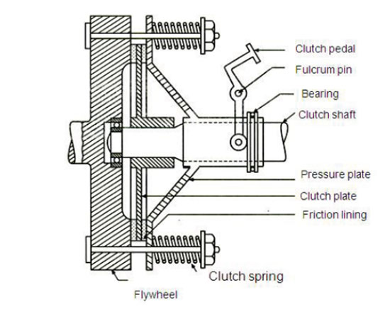
A flywheel is connected to the engine crankshaft and rotates with it. The pressure plate is bolted to the flywheel via clutch spring and it provides the axial force to keep clutch in the engaged position and is free to slide on the clutch shaft when the clutch pedal is pressed.
The friction plate is placed between a flywheel and a pressure plate. Friction lining is on both sides of the clutch plate.
Working
In the vehicle when the clutch is pressing the clutch for the disengagement of the gears the springs get compressed and the pressure plate moves backward. The clutch plate has become free between the pressure plate and flywheel. As a result of this, the clutch gets disengage and you are able to shift gear.
This makes the flywheel to rotate and as the engine is running and clutch shaft slows down the speed and stop rotating. After the pressing of the clutch peddles, the clutch is disengaged, and if not is remains to engage with spring forces. After releasing the clutch pedal, the pressure plate comes back to its original position, and then the clutch is again engaged.
Multi-Plate Clutch
The multi-plate clutch uses multiple clutches for making frictional contact with the flywheel of the engine. This transmits power between the engine shaft and transmission shaft of the vehicle. More number of clutches means more friction surface.
The increased number of friction surfaces increases the capacity of the clutch for transmitting torque. These clutch plates are fitted to the engine shaft and gearbox shaft.
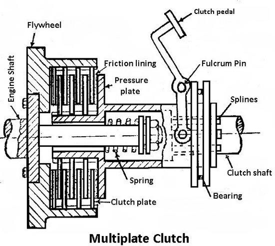
It is pressed by coil springs and it assembled in a drum. Each alternate plate slides in grooves on the flywheel and other slides on splines on the pressure plate. So, there is every different plate has an inner and outer spline.
The working principle of the multi-plate clutches is the same as a single plate clutch. Clutch is operating by pressing the clutch pedal. There are multiple clutches are used in heavy commercial vehicles, racing cars, and motorcycles for transmission of high torque.
There are two types of multiple clutches dry and wet. Now if the clutch is operated in an oil bath, known as a wet clutch. Now if the clutch is operated without oil it is known as a dry clutch. The wet clutches are mainly used with automatic transmission.
Cone Clutch
Below is the diagram of the cone clutch. It has friction surfaces in the form of cones. There are two conical surfaces for transmitting torque by friction. Engine shaft has a female cone and male cone. The male cone is mounted on the splined clutch shaft for slide on it and it has a friction surface on the conical portion.
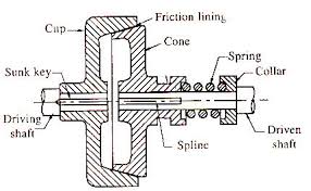
As the force of spring is engaged to the friction surfaces of a male cone are in contact with the female cone. As the clutch pedal is pressed the male cone slides towards to spring force and the clutch is disengaged.
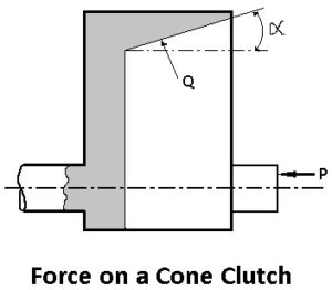
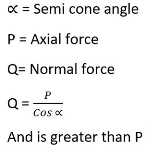
The advantage of using a cone clutch is the normal force is acting on the friction surface is greater than the axial force compared to a single plate clutch. Which is why the normal force acting on the friction surface is equal to axial force.
The cone clutches are not so much used because of the below disadvantages.
- If the angle of the cone is smaller than 20o, the male cone tends to bind in the female cone and it is become difficult to disengage the clutch.
- The small amount of the wear on the cone surfaces has a large amount of the axial movement of male cones which is difficult to allow it.
Centrifugal Clutch
For keeping the clutches in the engage position the centrifugal clutch uses the centrifugal force than the spring force. These types of clutch operated automatic depending upon the engine speed. Hence there is no clutch pedal is required to operate the clutch.
With this driver can easily strop the car without shifting the gear. In addition, you can start your vehicle by pressing the accelerator pedal in any gear.
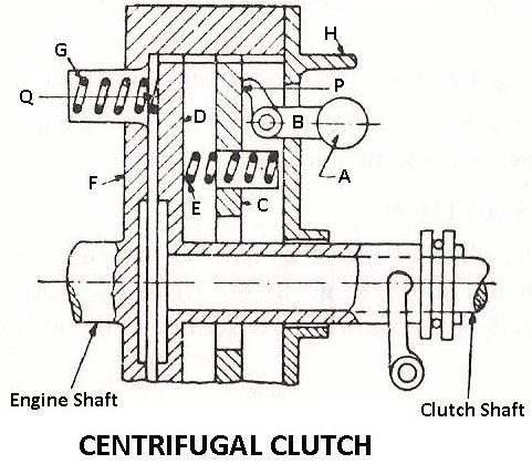
Working
- The centrifugal clutch weights A pivoted at B.
- When the speed of the engine increases the weights fly off due to centrifugal force, operates the bell crank levels and it presses the plate C.
- Movement of plate C presses the spring E and it presses the clutch plate D on flywheel than the spring G.
- In this process, the clutch is engaged.
- Spring G keeps the clutch disengage at low speed at about 500 rpm.
- The H limits the movement of weights due to centrifugal.
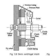
Semi-Centrifugal Clutch
The semi centrifugal clutch uses centrifugal force and spring force to keep in engaging position. The semi-centrifugal clutch consists of levers, clutch springs, pressure plate, friction lining, flywheel, and a clutch plate.
Construction of Semi-Centrifugal Clutch
The semi-centrifugal clutch consists of levers and clutch springs and are arranged equally on the pressure plate. Springs of the clutch are designed to transmit the torque at normal engine speed and the centrifugal force helps in torque transmission at a higher speed.
With the normal engine speed, the power transmission is low and springs engage the clutch and the weight levers do not make any pressure on the pressure plate.
With the high engine speed, the power transmission is high and weighs fly off and levers also exert pressure on the plate and keep the clutch firmly engage.
The semi centrifugal clutches have less stiff springs so the driver may not get strain while pressing the clutch. With the decrease in speed, the weight falls and the lever does not have any pressure on the pressure plate.
There is only spring pressure is applied to the pressure plate and it is enough to keep the clutch engage. The adjusting screw is fitted at the end of the lever and with that the centrifugal force on pressure plate can be adjusted.
Diaphragm Clutch
The diaphragm clutch has a diaphragm on conical spring which produces pressure on the pressure plate for engagement of the clutch. There is a spring in the form of a finger or crown type is attached on a pressure plate.
The tapered finger type spring is shown in the below image. This type of clutches has the engine power transmitted from crankshaft to flywheel. Flywheel has friction lining and it is connected shown in the below image. The pressure plate is provided behind the clutch plate as the pressure plate applies the pressure on the clutch plate.
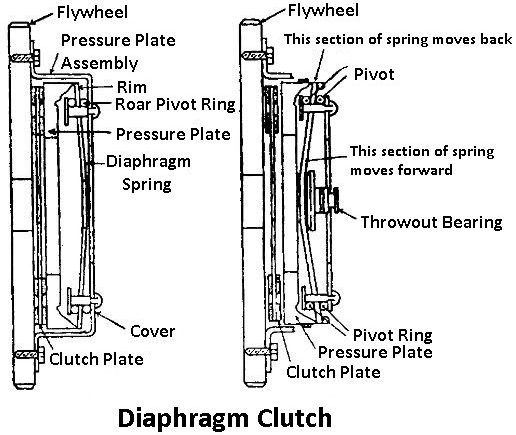
The diaphragm clutch is a conical shape of the spring. After pressing the clutch pedal the outside bearing moves towards the flywheel pressing the diaphragm spring which pushes the pressure plate backward.
With this, the pressure on the plate removes the clutch and is disengaged. When the pressure on the clutch peddle the pressure plate and diaphragm spring come back to its normal position and the clutch gets engaged.
Advantages
This type of clutch has no levers as the spring works as a series of levers.
Also, the driver does not need to apply heavy pedal pressure for holding the clutch disengaged with the coil spring type with the spring pressure increases more with the pedal as it depresses to disengage the clutch.
Dog and Spline Clutch
The dog is the clutch used to lock two shafts together or connect a gear and a shaft. Two parts of the clutch are one is dog clutch with external teeth and another is sliding sleeve has internal teeth.
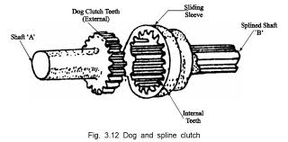
Both the shafts are designed as the one will rotate another at the same speed so they will never slip. When two shafts are connected then the clutch is engaged. For disengaging the clutch, the sliding sleeve moves back on the splined shaft for no contact with the driving shaft.
Dog and splined clutch are widely used in manual transmission vehicles for lock different gears.
Electromagnetic Clutch
The electromagnetic clutch is operated electrically but torque is transmitted mechanically. Because of this, the clutch is also called electro-mechanical clutches. With years it becomes an electromagnetic clutch.
These electromagnetic clutches have no mechanical linkage to control their engagement for fast and smooth operation. These electromagnetic clutches are suitable for the remote operation which means you can use it from distance.
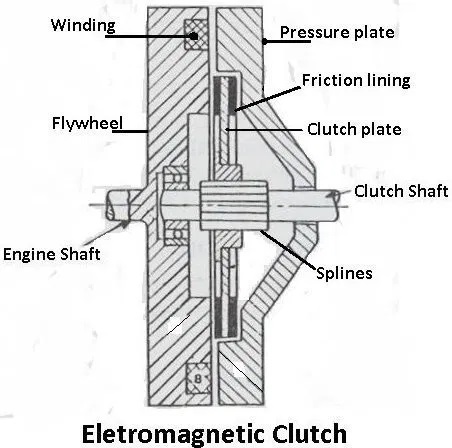
The clutch has a flywheel having to wind on it and the electricity is supplied by the battery. When the electricity is passing through winding it produces the electromagnetic field and attracts the pressure plate to get engaged. With the cut off in the electricity, the clutch is disengaged.
This clutch system has the gear lever having a clutch release switch and with that, the driver operates the gear lever to change gears the switch and is operated to cut off the current supply for winding and this disengages the clutch.
Vacuum Clutch
This type of clutch uses the existing vacuum in the engine manifold for operating the clutch. This vacuum clutch has a reservoir, non-return valve, vacuum cylinder with piston, and solenoid valve.
Working and Construction
As shown in the below image the reservoir is connected to the inlet manifold via a non-return valve. The vacuum cylinder is connected to the reservoir through a solenoid-operated valve. The solenoid is operating through a battery and there is a switch in the battery and is connected to the gear lever. The switch starts working when the driver changes the gear.
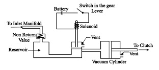
Now let’s see how it works. After the opening of the throttle, the pressure is increased in the inlet manifold and because of this, the valve of the non-return valve is closed. And this separates the reservoir and manifold so the vacuum can exist all the time in the reservoir.
With the normal operation, the solenoid valve is at the bottom position of the valve as shown in the image. And the gear lever remains open. Also, at this stage, the atmospheric pressure acts on both sides of the piston of the vacuum cylinder and due to this the vacuum cylinder is open to the atmosphere via the vent.
With the changes in the gear, the switch gets closed. Solenoid energized and pulls the valve with connects on one side of the vacuum cylinder to the reservoir. With this action, the passage between the vacuum cylinder and reservoir opens. With this difference in pressure, the vacuum cylinder piston moves forward and backward.
The piston movement is transferred by linkage to the clutch cause the disengage. When there is no movement in the gear, the switch is open and clutch remains to engage due to the force of springs.
Hydraulic Clutch
The working of the hydraulic clutch is the same as a vacuum clutch. The main difference is the hydraulic clutch is operated by oil pressure and the vacuum clutch is operated by vacuum.
Below is the image of the hydraulic clutch. This has fewer parts than other types of clutch. This clutch has an accumulator, control valve, cylinder having piston, pump, and reservoir.
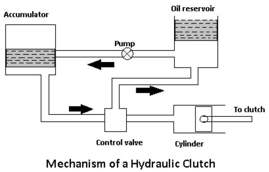
This oil reservoir pumps the oil into the accumulator via the pump. The pump is operated by the engine. The accumulator is connected to the cylinder via the control valve. The switch controls the valve and is attached to the gear lever and the piston is connected to the clutch by linking mechanism.
When the driver shifts the gear, the switch opens the control valve and this allows oil under pressure to the cylinder. Because of this oil pressure, the piston moves forward and backward which causes the clutch to get disengage.
When the driver leaves the gear lever the switch is open and it closes to the control valve and the clutch will be engaged.
Freewheel Unit
This freewheel unit clutch is known as spring clutch, overrunning clutch or one-way clutch. This is the most important part of every overdrive. Power transmission is in the one direction same as the bicycle. The freewheel unit is mounted behind the gearbox.
Power is transmitted from the main shaft to output shaft via driving the output shaft when the planetary gears are in overdrive. The flywheel unit has a hub and an outer race. This hub has internal splines is connected to the transmission of the main shaft.
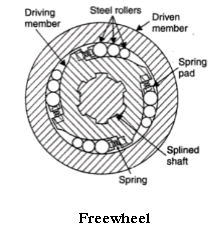
The outer surface of the hub has 12 cams and is designed for holding 12 rollers in a cage between outer race and hub. This outer race is spline to the overdrive of the outer shaft.
Working of the Freewheel
When the hub is driven in the clockwise direction the roller rides up the cams and by wedging action, they force the outer race for following the hub. So, the outer race moves in the same direction and at the same speed as a hub.
With the slowing down of the speed of hub, the outer race is moving faster continuously. The rollers move down cams and release the outer race from the hub. So, the outer race moves independently of the hub and the hub works as a roller bearing.
The main shaft of the transmission is connected to the hub and the output shaft is connected to the outer race. So, the freewheel unit can transmit power from the main shaft to the output shaft.
This is the information about the different types of a clutch. We have explained it with the diagram and the working of various types of clutch.
🔔We hope this information will help you. For more new information click on the notification button and get regular updates from Unbox Factory.
Now if you find this information helpful, share it with your friends, family, and colleagues.
If you like this post, let us know by comment below, if you want to add-on information about this topic, comment the information. We will consider the information if it is relevant.
Thank you for reading.


