Contents
- 1 List of Car Engine Parts | Working
- 1.1 The Car Engine Parts are as follows:
- 1.2 1. Cylinder Block
- 1.3 2. Cylinder Head
- 1.4 3. Crankcase
- 1.5 4. Oil Pan
- 1.6 5. Manifolds
- 1.7 6. Gaskets
- 1.8 7. Cylinder Liners
- 1.9 Comparison of the dry and wet liner
- 1.10 9. Piston Rings
- 1.11 10. Connecting Rod
- 1.12 11. Piston Pin
- 1.13 12. Crankshafts
- 1.14 13. Cam Shaft
- 1.15 14. Flywheel
- 1.16 15. Engine Valves
- 1.16.1 Construction of Engine Valve
- 1.16.2 Poppet Valve
- 1.16.3 Construction of Poppet Valve
- 1.16.4 Sleeve Valve
- 1.16.5 Construction of Sleeve Valve
- 1.16.6 Advantages of Sleeve Valve
- 1.16.7 Disadvantages of the Sleeve Valve
- 1.16.8 Rotary Valve
- 1.16.9 Advantages of Rotary Valve
- 1.16.10 Disadvantage of Rotary Valve
- 1.16.11 Which materials are used to make Valves?
- 1.17 16. Governor
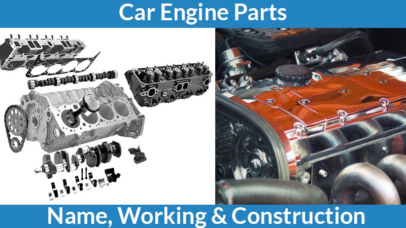
List of Car Engine Parts | Working
Here we have provide information about car engine parts with pictures. There are many engine components used to run an engine. Every part of an engine has its own importance in the working of the engine. As we all know an engine is a machine used to convert one form of energy into mechanical energy. The fuel is burning to create heat and it runs the engine.
There are two types of engines:
- Internal Combustion Engine
- External Combustion Engine
In the internal combustion engine, the fuel is burned inside the engine cylinder.
The external combustion engine is the fuel that is burning outside the cylinder engine.
The engine is very important in the automobile industry. And we don’t think about the automobile industry without an engine. We have explained the function and construction of car engine parts of an internal combustion engine.
Read Also: Otto CycleThe Car Engine Parts are as follows:
- Cylinder Block
- Cylinder Head
- Crank Case
- Oil Pan
- Manifolds
- Gasket
- Cylinder Liner
- Piston
- A Piston Ring
- Connecting Rod
- Piston Pin
- Crank Shaft
- CamShaft
- Flywheels
- Engine Valves
- Poppet valve
- Sleeve valve
- Rotary valve
- Governers
Now let’s start the list of Car Engine Parts and its explanation.
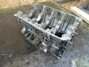
1. Cylinder Block
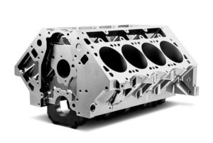
The above image shows the cylinder block. The cylinder block is a framework of the engine and also the main car engine part. Cylinder block, cylinder head, and crankcase are the main three parts of the engine and main body of the automobile engine. The cylinder block is one of the important car engine parts.
It has mainly three parts:
- Cylinder where piston slid up and down.
- Port
- Passages for the flow of cooling water.
How Cylinder Block Works?
- Generally, the cylinder block is made of grey cast iron or aluminum and its alloys.
- The crankcase is fixed to the bottom and other parts like timing gear water pump, ignition distributor, flywheel, fuel pump, etc. are also attached.
- There are passages in the cylinder walls for the circulation of cooling water.
- The mating surfaces of the block are machined very carefully for the perfect sealing surface.
- There is lubrication oil in the cylinder block for other engine components and it flows through drilled passages known as oil galleries.
2. Cylinder Head

- Cylinder heads are generally made with cast iron and aluminum alloy.
- The top of the cylinder is covered by a separate cast piece known as a cylinder head.
- It is attached to cylinder block by studs to fix the block gaskets which provide a tight, leak-proof joint between head and block.
- There is a combustion chamber is in every cylinder head which is above the cylinder.
- In the cylinder head, there are also valve guides, valve seats, ports, coolant jackets and threaded holes for a spark plug. There is also a passage for flowing of cooling water.
Application of Cylinder Head
- In some cases, the cylinder head casts integrally with cylinder blocks for the gas-tight joint.
- Detachable head types have more advantages than the integral construction.
- For some heavy-duty engine requires high cooling rates like in racing cars and for that copper alloys are used.
Types of Cylinder Head
The cylinder head types are depending upon valve and port layout and are classified into below types:
- Loop flow type
- Offset cross-flow type
- Inline cross-flow type
In the Loop Flow Type, the inlet and exhaust manifolds are on the same side this is easy for preheating the intake air.
The Offset cross-flow type the inlet and exhaust manifolds are placed on different sides of the cylinder head.
Inline cross-flow type, the valve is positioned transversely and it is inclined to each other. The inlet and exhaust manifolds are on different sides of the cylinder head. This gives better performance but this setup is costly.
3. Crankcase
Oil pan and lower part of the cylinder block are called the crankcase. The crankshaft is fitted at a bottom portion of the cylinder block.
Construction
- The crankcase is made of grey cast iron or aluminum. It may integrate with the block or can cast separately and then attached to block with bolts.
- It looks like there is a box with no bottom. The Oil pan or sump forms the bottom half of the crankcase.
Working
- The main function of the crankcase is to provide support for main journals and bearing of the crankshaft and maintaining the axes of rotation under various engine loads.
- The crankcase is supporting the number of bearings known as the main bearing.
4. Oil Pan
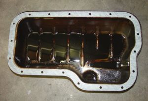
The bottom half of the crankcase is called an oil pan or sump. The oil pan is connected to crankcase vi screws and to make it leak-proof the gaskets are used. An oil pan is a reservoir for the storage, cooling, and ventilation of engine lubricating oil. The oil pan is one of the important car engine parts.
There is the drain plug at the bottom of the oil sump to drain out the dirty oil at the time of oil replacement. A sump is made of pressed steel sheet or aluminum alloy cast.
Functions of the Oil Pan
- It is used to store oil for the engine lubrication system.
- Oil Pan is used to collecting the return oil draining.
- It is also used as a container for impurities or foreign matters.
- An oil pan is used to provide for the cooling of the hot oil in the sump.
Working
- The oil pump in the lubricating system draws oil from the oil pan and sends it to all working parts of the engine.
- Oil drains off and runs down into the pan.
- There is a constant circulation of oil between the pan and working parts of the engine.
5. Manifolds
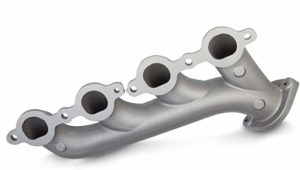
Manifolds are the sets of pipes attached to the cylinder head which carry air-fuel mixture and exhaust gases. The manifolds are made of cast iron so they can bear the high temperature of the exhaust gases.
Construction
It has air intake, throttle body, intake manifold flange for tail-pipe and flange for a carburetor.
Working
- Air goes into the air intake and travels through the throttle body into the intake manifold and from there is goes into the engine via cylinder head.
- The inlet manifold carries the air-fuel mixture from carburetor to the cylinders.
- The exhaust manifold is a set of pipes carrying exhaust gases from the cylinder head to the exhaust system.
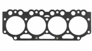
6. Gaskets
Gaskets are providing the tight-fitting joint between two surfaces.
They are used in
- The joint between the cylinder head and the cylinder block
- Between crankcase and oil pan
- Between cylinder block and manifold.
Which materials are used for Gaskets?
Cork, Asbestos, Rubber
Properties of the Gasket
- Conformity: It has to conform to the mating surface which may have roughness or warpage.
- Resistance: It should have resistance to high pressure, extreme temperature, and vibrations.
- Impermeability: Gasket must impermeable to the fluid.
- Resistance to chemical attack: Gasket should be resistant to chemicals like fuel, products of combustion, coolant and engine oil.
- Provision of Apertures: Gasket must apertures to studs, bolts, opening, etc.
Which types of gaskets are used in Engines?
- Copper-asbestos gasket
- Steel-asbestos gasket
- Steel-asbestos-copper gasket
- Single steel ridged or corrugated gasket
- Stainless steel gasket.
7. Cylinder Liners
There are cylindrical shapes are used to avoid the problem of cylinder wear. It is one of the most important functional parts for making up the interior of an engine.
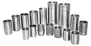
The cylinder liners are replaced after they are worn out. These cylinder liners are made of iron alloy and contain silicon, manganese, nickel, and chromium.
The cylinder liners are cast centrifugally and are resistant to wear and corrosion. These cylinder liners are of oil hardening type and provide longer life to the engine.
What are the types of Cylinder Liners?
- Dry Liners
- Wet Liners
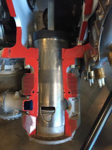
Dry Liners
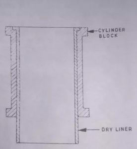
In the above image, the construction of the dry liner is shown. The liner is made in the shape of a barrel with a flange at the top to keep into position.
The entire outer surface bears against the cylinder block casting and it will be machined accurately at both outer and inner faces.
If the liner is loose, the heat dissipation becomes poor and lose contact with the cylinder block.
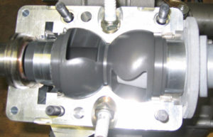
Wet Liners
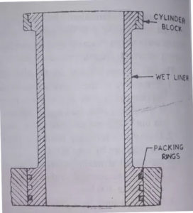
The above figure shows the wet liner. This type of liner has direct contact with the cooling water at the outer face.
So, these liners do not require to be machined accurately at the outer surface. But they to machined accurately at the inner surface.
These are resisting corrosion with continuous contact with cooling water and are coated with aluminum at the outer surface.
Comparison of the dry and wet liner
Dry Liners
- It is provided in the original design or afterward.
- Construction of the cylinder block is very complicated and the cooling effect is not so good.
- It is very important for dry liners to machining accurately to make contact with the cylinder.
- The leak-proof joint is not necessary and cannot be finished before fitting.
Wet Liners
- The wet liners have to be included in the original design. The construction of the cylinder block is simple.
- The cooling effect is better as the liner has direct contact with the cooling water.
- The accurate machining is not required and has finished before fitting.
- There should be a leak-proof joint between the wet liner and cylinder block.
8. Pistons
Pistons are the most important car engine parts. The cylindrical plug that moves up and down in the cylinder.
Pistons convert pressure energy from the burning of fuel into mechanical power and transfer this power to a crankshaft via a connecting rod.
The highest position of the piston reaches in the cylinder is called Top Dead Center TDS
The lowest position is called Bottom Dead Center BDC.
3 to 5 piston rings provide a good seal between cylinder wall and piston. As the piston is important for the engine the economy and efficiency are depending on the working of the piston.
Pistons are made of,
- Cast Iron
- Aluminum alloy
Today the aluminum alloys are widely used and they are cast or forged.
The piston must-have properties like
- Rigidly withstanding to high pressure
- Must be light in weight which reduces the reciprocating mass to perform at higher engine speed.
- Must have good heat conductivity.
- Make less noise while operating.
Piston Clearance
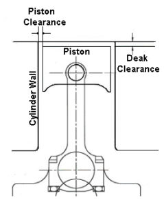
A piston is small in diameter than the bore of the cylinder. Space between cylinder and cylinder wall is called piston clearance. Piston clearance provides space for a layer of lubricant between piston and cylinder wall to reduce friction.
Normally piston clearance is
0.025mm to 0.100mm
The distance between the piston and cylinder should be maintained.
- If there is less clearance there will be a chance of power loss from excessive friction, more wear, seizing of the piston in the cylinder.
- If there is more clearance, the piston slap will occur. The piston slap is a sudden tilting of a cylinder as the piston moves down during the power stroke.
This prevents piston seizures due to high temperatures. If there is no clearance, it is not possible to reciprocate the piston inside a cylinder.
Function of the Piston
- It has to transmit the power developed by fuel combustion to the crankshaft through the connecting rod.
- Piston forms a seal so the high-pressure combustion gases do not escape to the crankcase.
- It works as a support for the small end of the connecting rod.
- The piston should suck the charge and push the exhaust gases.
Features of the Piston
- The top of the piston is known as head or crown.
- There are make the few grooves to cut to house the piston rings. Bands left between grooves known as lands.
- The below par of piston is called the Skirt and has bosses on the inside to support the piston pin.
- Distance between the axis of piston pin and top of piston crown is called compression height.
Different Types of Pistons
The pistons are divided according to their shape, design, and operation. Below are the types of the piston:
- Cast Iron Piston
- Forged Pistons
- Cast Steel Piston
- BI-metal Piston
- Two-piece Piston
- Oil-cooled Piston
- Anodized Piston
- Tinned Piston
Pistons are made from materials like Cast Iron, Aluminium, Lo-Ex Alloy, Invar, Steel alloy.
Protective Coating like Cadmium plating, Anodised Pistons, Tinned pistons, Chromium Plating.
9. Piston Rings
The piston rings are fitted into grooves of the piston to maintain a seal between the piston and cylinder wall.
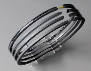
There are different piston rings are used from 2 to 4 compression rings and 1 to 2 oil control rings are used but today usually there are only three are used and one of them is used in the oil control ring.
Function of Piston Rings
- It is used to make a seal stop the high-pressure gases from the combustion chamber to enter into the crankcase.
- These piston rings provide passage for heat flow from piston crown to cylinder walls.
- The piston rings are also maintaining lubrication oil in cylinder walls to the entire length of piston travel and this minimizes the cylinder wear.
Construction of Piston Rings
- A piston ring is cast individually and machined carefully when it is in the position to exert uniform pressure against the cylinder walls.
- The gap has been cut at the end.
- Piston ring end gap is kept about 0.30 to 0.35mm when it is installed.
- Gap between piston and cylinder is closed when the piston is in the cylinder.
Piston Ring end gap may
- Butt type
- Taper type
- Lap type
Which Material is used for Piston Rings?
The fine-grained alloy cast iron having silicon and manganese is used. These piston rings are good heat and wear-resisting qualities.
The chromium-plated rings are used for the top ring and it has to work on the highest temperatures and has the corrosive action of combustion products.
Different Types of Piston Rings
There are mainly two types of piston rings.
Compression Rings
These rings effectively seal the compression pressure and the leakage of combustion gasses. These rings are fitted in the top grooves. They also transfer heat from the piston to cylinder walls.
Oil Control Rings
Main function of the oil ring is to scrape the excess oil from the liner and return it back to the oil sump during the downward and upward movement of the piston. This prevents oil from reaching the combustion chamber. There is one of two oil control rings is used in the piston. If there are two rings are used in the piston one is fitted above and the other is fitted below the gudgeon pin in the piston. There are drain holes or slots in the piston rings. These slots allow the scrape oil to reach into the oil sump via piston holes.
Read Also: Carburetor10. Connecting Rod
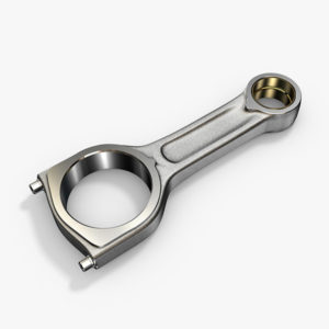
The above figure is of a connecting rod. The connecting rod is fitted between a piston and crankshaft.
Connecting rod should be light and strong to withstand the stress and twisting force.
Construction of Connecting Rod
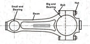
- Connecting rod has an I-beam cross-section and it is made of alloy steel of duralumin with drop forging.
- Today it is also cast from malleable or spheroidal graphite C.I.
- Small end of the connecting rod is made of a solid eye and it is used to connect the piston by piston pin.
- The big end of the connecting rod is split and used to connect the crankpin of the crankshaft.
11. Piston Pin
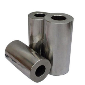
Piston pin is also called a wrist pin or gudgeon pin. The piston pin is used to connecting the small end of the connecting rod and piston.
Construction of Piston Pin
The piston pins are made hollow to reduce weight and it is made from case hardened steel.
There are mainly three types of piston pins:
- Set screw type
- Semi-floating
- Fully floating
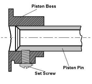
The above image shows the set screw type piston pin. The pin is fastened to the piston to the piston by a set screw like the connecting rod end swivel has required by the combined reciprocating and rotary motion of the piston and crankshaft.
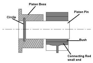
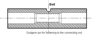
The above image is a semi-floating piston pin and it is fastened to the connecting rod with a clamp screw.
The fully floating piston pin is shown in the above image. This pin floats in both piston bosses and small end of connecting rod. This prevents the contact with cylinder wall by two circlips.
12. Crankshafts
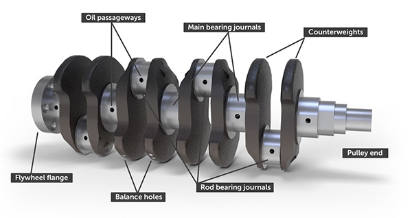
The crankshaft is a very important car engine component where power is taken. Crankshaft is a main power transmission source in all engine components.
It is an important part of a power transmission system where the reciprocating motion of the piston is converted into the rotating motion with the connecting rod.
Construction of the Crankshaft
- The crankshaft is also another important car engine parts.
- The crankshaft is made of casting or forging of heat-treated alloy steel and it is machined.
- Crankshaft has crankpins, weds, balancing weight, main journals, and oil holes.
- Big end of the connecting rod is connected to the crankpin of the crankshaft.
- The center to center distance between the crankpin and crankshaft has half of the piston displacement during the stroke.
- There is one complete revolution of the crankshaft that makes two strokes of the piston.
Parts inside the main bearing are called the main journals.
The balancing weights are provided on the opposite side wed for balancing. The crankshaft has drilled oil passages through which oil flows the main bearing to the connecting rod bearings.
There are three components in the crankshaft
Gear drives the camshaft
Vibration damper control torsional vibration
Fan belt pulley drives the engine fan, water pump and a generator with V-belt.
There is flywheel at the rear end of the flywheel. It is for constant running the crankshaft.
On the rear end, the main journal and oil seal is fitted. There are also oil return threads in some engines for returning the lubricating oil to the sump.
There are mainly two types of crankshafts,
In one-piece type, all the parts are integral and formed by drop forging and then machining.
In the build-up type, the crankpins and journals are fastened to crank webs.
13. Cam Shaft
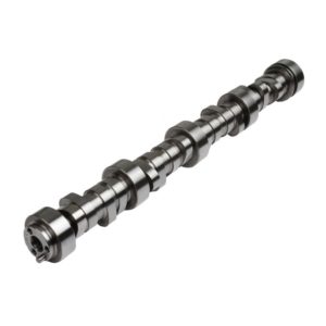
The cams are mounted on the camshaft. The cam changes the rotary motion of the camshaft to the linear motion of the follower. The opening of the valves depends on the camshaft.
Construction of Camshaft
- There are numbers of cams on the camshaft and with the length, there are two cams for each cylinder. One of the cams uses to operate the inlet valve and other for the exhaust valve.
- Also, the camshaft operates the fuel pump and gear to drive the ignition distributor and oil pump.
- A camshaft is driven by the crankshaft. Camshaft gear has twice the teeth then the gear on the crankshaft.
- Camshafts are made from forged alloy steel.
This has a 1:2 gear ratio, camshaft turns at half speed of the crankshaft.
Working of Camshaft
Two revolutions of crankshaft make one revolution of a camshaft and there is one for opening and one for a closing valve in the four-cylinder engine.
So, the correct opening and closing of the valves take in relation to the position of the piston in the cylinder.
There are three types of a camshaft drive mechanism,
- Gear drive
- Chain drive
- Belt drive
14. Flywheel
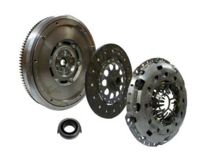
A flywheel is used in a transmission system of the vehicle.
Construction of Flywheel
- A flywheel is a heavy steel wheel attached to the rear end of the crankshaft.
- Size of the flywheel depends on the number of cylinders and construction of the engine.
Working of Flywheel
- In the power stroke the engine speeds up and in other strokes, it is slow down.
- But the inertia of the flywheel is to keep running off the crankshaft at a constant speed. The engine speed is maintained constant.
15. Engine Valves
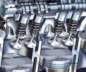
The engine valves are very important to control the timing of the air-fuel mixture entering into the cylinder and combustion products out from the cylinder.
Construction of Engine Valve
- These engine valves are located at the inlet and outlet opening of the engine cylinder.
- These valves fit on the valve seats in the closed position.
There are three types of engine valves,
- Poppet Valve
- Sleeve Valve
- Rotary Valve
Poppet Valve
The poppet valve is a widely used valve in automobile engines. It is called the poppet valve because of its motion of popping up and down.
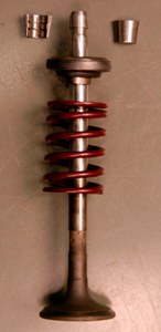
Construction of Poppet Valve
The Poppet valve has a head and a stem. The valve has an angle of 30o to 45o and it is ground perfectly as it has to match with the valve seat for perfect sealing.
Stem has a spring retainer lock groove and the stem end is in contact with cam for up and down movements of the valve.
Sleeve Valve
As the name, there is a tube or sleeve kept between the cylinder wall and the piston.
Construction of Sleeve Valve
The inner surface of the sleeve forms the inner cylinder barrel where piston slides.
The sleeve has continuous motion and admits and drives out of gases by virtue of periodic coincidence of port cut in the sleeve with ports formed through main cylinder casting.
Advantages of Sleeve Valve
- It has a simple construction.
- This valve has a silent operation.
- There is no noise as valve cams, racker arm, tappets valves, etc. are not making any noise.
- It has less tendency for detonation.
- There is good cooling as the valve is connected with water jackets.
Disadvantages of the Sleeve Valve
- High oil consumption for lubrication as a larger area of sleeve surface to be lubricated.
- The cleaning of ports and valve is complicated.
Rotary Valve
The above image is of a rotary valve. There are many types of rotary valves. There is a disc rotating and has a port. In the rotating, it rotates alternately with the inlet and exhaust manifolds.
Advantages of Rotary Valve
- The rotary valves have a simple construction.
- The manufacturing cost of a rotary valve is cheaper.
- It is suitable for high-speed engines.
- There are fewer stresses and vibrations compared to poppet and sleeve valves.
- These are smooth in operation and also uniform and has the noise-free operation.
Disadvantage of Rotary Valve
- There is difficulty in pressure sealing between the rotary disc and cylinder.
- Valve lubrication is difficult.
Which materials are used to make Valves?
For the making of inlet and exhaust valves, the different material is used as both have to work in different condition.
There is Silico-chrome steel is used for inlet valves. And for exhaust valves, the molybdenum is added to silico-chrome.
Recently the materials like austenite steel and precipitation hardening steel is used.
16. Governor
For the petrol engine the carburetor control both air and fuel supply to the engine cylinder under speed and load conditions.
The supply of air-fuel mixture is varying to meet the given condition. But for the diesel engine, the governor is used to keep the engine speed within limits.
The main function of the governor is to regulate the supply of the fuel with the help of mechanism so the engine speed remains within the range.
How Governor work?
With the increase in load, the engine speed is decreased.
With the decrease in load the speed increases.
If there is no governor the engine speed increases at lighter loads and the dynamic stresses damage the engine parts.
Governor is set for maintaining particular engine speed and operates a mechanism as more fuel is injected to increase the engine power.
Governor is also used to reduce the supply of fuel in the engine. It is very important to keep engine speed within limits.
Different types of Governor
- Mechanical or Torque Control or Centrifugal Governor.
- Pneumatic Governor.
- Hydraulic Governor.
This is the information about important car engine parts. There are also many other car engine parts used to make an engine. We have explained different car engine parts with its function, how these car engine parts work and its advantages and disadvantages and how they made.
🔔We hope this information will help you. For more new information click on the notification button and get regular updates from Unbox Factory.
Now if you find this information helpful, share it with your friends, family, and colleagues.
If you like this post, let us know by comment below, if you want to add-on information about this topic, comment the information. We will consider the information if it is relevant.
Thank you for reading.


