Contents
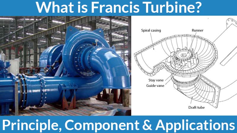
Francis Turbine
The Francis Turbine is a combination of impulse and reaction turbine and the blades are rotated in both reaction and impulse force of water flowing through them. This helps to produce electricity more efficiently. It is used for the production of electricity in hydropower station.
James B. Francis is an American civil engineer who mixes the impulse and reaction turbine. And in this, the water enters the turbine radially and exits axially. The original process is completed with a unique design of the blade. And these blades are rotate both using reaction and impulse force of water flowing with them.
Francis turbine can produce both kinetic and potential energy for producing power. There is also a wide range of water heads available. And this could be used for the head as low of 50m to high as 400m. With these heads, the flow can be controlled from 10 meter-cube per second to high as 700 meter-cube per second.
The Francis Turbine is also called a mix flow turbine. And it is the best modern turbine to date. Francis Turbine is widely used in hydro-power plants.
In this article, we will discuss Francis Turbine’s working principle, its main components, and the application.
Read Also: All about Kaplan TurbineFrancis Turbine Working Principle
The blades of Francis Turbine is designed as one portion of the blade creates the pressure difference between opposite faces of the blade when water flows through it. And the second part of the blade design uses the impulse force of water hitting it and this action of pressure difference and this impulse force generates enough power to get the turbine moving at the required speed. Because of this, there is a decrease in kinetic and potential energy of water at the exit and when it enters the turbine.
This design helpful for both the reaction and impulse force to generate the power better than the impulse and reaction turbine individually.
Main Components of Francis Turbine
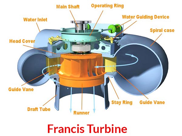
Spiral Casing
The spiral casing has uniformly decreasing cross-section area with a circumference. This decreasing the cross-section area. This makes sure that there is the uniform velocity of water striking runner blades, as in the openings for water flow in-to runner blades from the very starting of the casing. So, the flow rate would decrease as it travels along the casing. So, the cross-section area is reduced to make pressure uniform and this process strikes the runner blades.
Stay Vanes
The stay and guide vanes are guiding the water to the runner blade. The stay vanes remain stationary for their position and reduce the swirling of water due to radial flow and it enters into runner blades which make the turbine more efficient.
Guide Vanes
After passing through stay vanes and glides through guide vanes to enter runner blades. The guide vanes can change their angle so it can control the angle of attack of water to the runner blades which make them work properly. Also, they regulate the flow rate of water into runner blades to controlling the power output of a turbine according to the load on the turbine.
Runner Blades
The design of a runner blade decides the performance of the turbine. The runner blades of mixed-flow turbines divided into two parts, the upper part of the blade use the reaction force of water flowing and the lower half is in the shape of a bucket with impulse action of water flowing through it. The above forces make the runner rotate.
Draft Tube
The draft tube connects the runner exit to the tailrace. The cross-section area is increases with the length. And when the water came out from runner blades is at low pressure. Expanded cross-section area help to recover the pressure as it flows towards the tailrace.
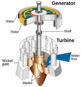
How does it work?
The water enters into the turbine via spiral casing and after that, it enters into runner blades and passes through stay and guide vanes. Ahead moves with the length of casing into decreasing the cross-section area of the spiral casing and it ensures the pressure energy of water remains uniform with-it length. The other portion of water is entering into runner blades and it reduces the flow rate with the length of casing. Stay vanes are not moving and this eliminates swirls from the water. And it is generated because of flow via spiral casing. And makes the water flow linear for deflecting by guide vanes.
The guide vanes angle decides the angle for water flowing to runner blades and it ensures the output from the turbine. Also, the guide vanes control the flow rate of water into runner blades. It act as a load on the turbine. In the Francis turbine, the runner blades are stable and are cannot move and change the angle. It is the guide vanes that control the power output of the turbine.
In the Francis turbine, the upper part of the runner blade is designed to create pressure between opposite faces of a blade. By water flowing through it which is the same as air-foil uses the pressure for lift force. The extra part of the turbine is designed like a bucket to use water’s kinetic energy. The runner blades use both pressure energy and kinetic energy of water to rotate the runner fluently.
Water coming out of runner blades don’t have kinetic energy and pressure energy. The draft tube is used to get back the pressure for the tailrace. And is still cannot recover the pressure that we can stop air to enter into the runner which causing the cavitation.
Now What is Cavitation?
The pressure difference of water entering the turbine and it exists after the striking as the runner blades are high. And because of this pressure difference air molecules are at high pressure when water is coming out and it enters the turbine casing in the form of bubbles. These bubbles are exploding near the surface of runner blades and it causes the shock wave, and this produces a defect at runners’ surface and it is called cavitation and this causes a dangerous problem for turbine efficiency. How to prevent the blades from cavitation? The solution is using the hard surface material like stainless steel or go for surface hardening of runner blades for preventing cavitation.
Applications of Francis Turbine
Francis Turbine is widely used as a turbine in hydro-power plants for generating electricity.
It is also used for irrigation to pump water from the ground.
The Francis Turbine is efficient with the range of water head and flow rate.
Francis Turbine is the most versatile and efficient hydro-turbine till date.
This is the information about the Francis Turbine and Francis Turbine working.
🔔We hope this information will help you. For more new information click on the notification button and get regular updates from Unbox Factory.
Now if you find this information helpful, share it with your friends, family, and colleagues.
If you like this post, let us know by comment below, if you want to add-on information about this topic, comment the information. We will consider the information if it is relevant.
Thank you for reading.


