Contents
- 1 What is the Steering System?
- 1.1 First What is Steering System and What are the types of steering systems?
- 1.2 How does Car Steering Works?
- 1.3 Why the Steering system is Important?
- 1.4 What are the functions of the Steering System?
- 1.5 What is Wheel Alignment?
- 1.6 How many types of steering systems in the Automobile?
- 1.7 Why caster is required?
- 1.8 Main functions of Kingpin Inclination
- 1.9 Different types of steering system depend upon Leverage
- 1.9.1 Reversible Steering
- 1.9.2 Irreversible Steering
- 1.9.3 Steering Gears
- 1.9.4 1. Recirculating Ball Steering Gear
- 1.9.5 2. Rack and Pinion Steering Gear
- 1.9.6 3. Worm and Sector Steering Gear
- 1.9.7 4. Worm and roller steering Gear
- 1.9.8 5. Worm and Ball Bearing Nut Steering Gear
- 1.9.9 6. Cam and Roller Steering Gear
- 1.9.10 7. Cam and Peg Steering Gear
- 1.9.11 8. Cam and Double Lever Steering Gear
What is the Steering System?
What is steering system, how does a steering system work, what are the types of the Steering system, Steering Assembly? You will get all answers in this post.
First What is Steering System and What are the types of steering systems?
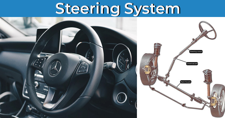
The steering system or car steering system is a very important part of any automotive vehicle. Steering system has to respond well while driving and the steering control makes you safe in driving.
The steering system is very important in the automobile as it is controlling the direction of the vehicle by turning it properly. This system controls the front wheels. To control the vehicle in different speed modes with safety the accurate steering is required.
With this system, the driver has to apply little force to steer the vehicle.
The steering is possible by turning the rear wheel and it is widely used in low-speed slow floor vehicles and for applications like lifting and transporting the heavy parts for short distance like a forklift.
Generally, the automobiles always have front-wheel steering and above is the car steering system diagram.
To move the steering of the vehicle is very easy, the working of the steering system is quite complicated. Let’s see how your vehicle turns easily.
When you turn the steering vehicle, the steering shaft rotates the pinion gear. Teeth of the pinion gear interlocks with the steering rack when the pinion rotates and this rotation will push the rack and when the rack moves it attached rods and the steering knuckles act as pivot points and turn the front tires of the vehicle.
When rotating the steering wheel to left it will push the rack to the right pivot the front tire to left.
If the steering wheel is moving more the more rack is pushed and has the sharper turn. You don’t have to worry about how does it work but our purpose is to explain how exactly is working when you move your steering wheel.
There are many moving parts in the steering system used to steer any automobile.
How does Car Steering Works?
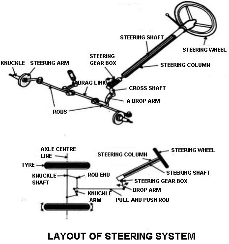
Steering system converts the rotary motion of the steering wheel into the angular turn of the front wheels.
- The steering wheel rotates the steering column.
- The steering gearbox is fitted to the end of the column. So, when the wheel is rotated the cross shaft oscillates in the gearbox.
- Cross shaft is connected to the drop arm and it is linked using drag link to the steering arms.
- Cross shaft is connected to the drop arm and it is linked to drag link.
- When the steering wheel steers the knuckle moves to and fro and moving the steering knuckle and it connected.
- The one end of the drag link is connected to the tie rod and the other end is connected to the end of the drop arm.
Why the Steering system is Important?
The steering system is very important and it is required to control the vehicle on various speed ranges with safety and easy for a driver on various driving conditions.
For better performance of the vehicle, it is required that the vehicle should be in control of the driver. So, the control of the vehicle is done by the steering system and it provides the steer to the automobile.
What are the functions of the Steering System?
- The driver can control the vehicle as required with a steering system.
- The steering provides stability to a vehicle on different road conditions.
- It reduces tire wear and tear.
- The system prevents road shocks to reach the driver.
- Also, the most important the steering provides self-rightening after taking the turn.
What is Wheel Alignment?
The wheel alignment is the correct adjustment of pivot axes that controlling the movement of the wheels.
The wheel alignment is the position of front wheel and steering mechanism for the easy steering and this reduces the tire wear and provides stability in driving.
The better wheel alignment provides,
- Steering comfort
- Has uniform wear of the tire
- Low energy consumption
- Has minimum vibrations
- No wheel wobbling
- Minimum effort to turn the vehicle
- For achieving self-centering of the wheel after turning
- For achieving directional stability of the vehicle while running
How many types of steering systems in the Automobile?
There are three types of a steering system:
- Bicycle steering
- Turntable steering or center pivot steering
- Ackerman steering or side pivot steering
First, let’s see Bicycle Steering
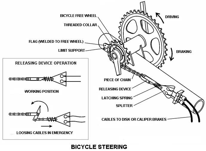
In this type of steering system, the rear type is fixed and the front tire is steered and for a safe turning it is important to both the wheels must roll about a point. When front-wheel produce cut and the addition of perpendicular of the rear wheel and that point is said as an instantaneous center.
2. The turntable of Center Pivot Steering
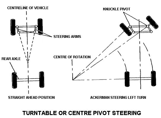
For the four-wheel-drive vehicle, the front two wheels are mounted on axle and the axle in turning is fix and has a single pivot.
When the front wheels of the vehicle are turned the whole front axle is turned to a central pivot. The perpendiculars of the wheels are meet at the point in any turn so the turning is safe and wheels have roll free operations.
The turntable steering system is widely used in horse-drawn coaches and trails. This steering system is unsuitable for automobile vehicles as it is unstable at high speeds. Also, the center pivot steering system requires more space as the whole axle has to turn.
3. Ackerman Steering or Side Pivot Steering
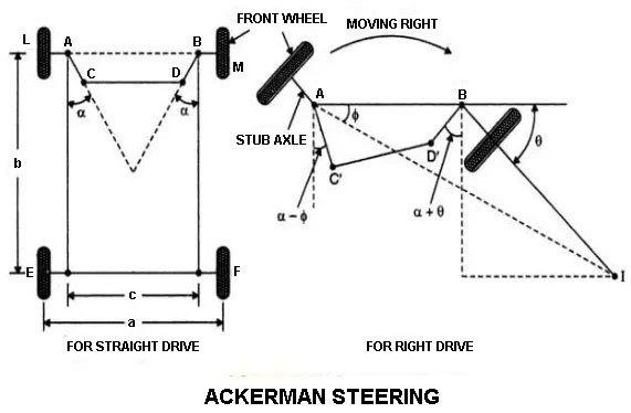
This is the widely use steering system in most automotive. The front wheel is turned individually about the side pivot.
In this type of steering system, the front axle is pivoted on either side of the axles and as there are stub axles, the wheels are mounted. These stub axles are turned by steering connected to tie rod.
This steering arm is not parallel they are inclined. The lined made via inclined arms and it will meet at the center of rear axle line and forming an angle is called Ackerman Angle.
The below factors are important to understand for proper alignment:
- Camber (wheel rake of Camber angle)
- Caster
- King pin inclination
- Toe-in
- Toe-out
Camber
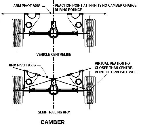
The camber is the angle between the centerline of the tire and vertical line as it is viewed from the front of the vehicle. If the wheels are tilted outwards at the top is known as positive camber and if tilted inward is called negative camber. There is an equal angle is provided on both front wheels.
In the positive camper, the wheels become vertical under load on the tire have full contact with the road and the tire wear is uniform. If there is positive camber is more than the tire outer edge of the rear tire wear out very quickly. And if there is negative camber is more than the inner edge will wear out quickly.
The unequal camber on both front wheels causes the wheel vibration at low speed. The older models have considerable camber. The modern-day cars use the proper design and materials which have little camber. It should not have to more than 2o. The Camber of the modern vehicle is adjusted by an eccentric cam for control am shaft.
Caster
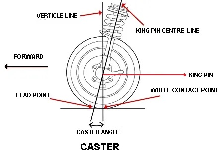
The kingpin axis or steering axis is tilted forward or backward from the vertical line and this tilt is known as Caster. The Caster Angle is an angle formed by the forward or backward tilt of the steering axis from vertical when it is a view from the side of the wheel.
The backward tilt is known as a positive caster and the forward tilt is known as negative caster. And if the caster is not equal on both sides, the vehicle pulls to the side of the wheel having less caster angle. The modern-day vehicles have the caster angle between 2o to 8o.
Why caster is required?
- For maintaining directional stability and control.
- For increasing steering stability.
- Reduces drive effort to turn the vehicle.
King Pin Inclination
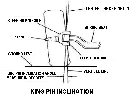
The king pin inclination is an angle between the vehicle line and center of kingpin or steering axis and it is viewed from the front of the vehicle.
The modern cars have kingpin inclination varies from 7oto 8o. It should have equal on both sides. This is greater on one side than the other and the vehicle has to pull the side having a greater angle.
Main functions of Kingpin Inclination
- This helps in the self-centering of wheels after taking a turn.
- For providing directional stability.
- For reducing steering effort.
Toe-in
The front wheels are tilted inward at the front of the distance between the front wheels at the front A is less than the distance at its rear B and it is measured at height of hub level and the center of the wheel tread.
There is about 2 to 3 mm difference between Toe-in (B-A). And the purpose of the toe-in is to overcome the bad effect of the camber. It is adjusted by tie-rod ends.
Toe-out
When a vehicle is turning with the Ackerman steering the inner wheel turns more degree and the outer wheel the perpendiculars of four-wheel at a point when it produced. The point is called the instantaneous center so the wheels roll very easy without scuffing.
Different types of steering system depend upon Leverage
There are mainly two types of steering depend upon the leverage provide between road wheel and steering wheel and the number of shocks and vibrations transmitted from road wheels to steering wheels are:
- Reversible Steering
- Irreversible Steering
Reversible Steering
The gear ratio in reversible steering is 1:1 like a bicycle or scooter steering. The gear case is an angular movement of the handle and it causes the identical angular movement to the wheel and the wobbling or vibrations of the wheel are transmitted to the steering handle. The arrangements are suitable for bicycles, motorcycles, scooters, etc.
Irreversible Steering
The gear reduction ratio between the wheel and steering wheel is very high. The road roller has about 40:1.
In this, the very high gear reduction is necessary as the load carried on wheels are very high. This type of steering has no transmission of notion due to the vibration of the wheel from road wheels to steering wheels.
Steering Gears
Now the steering wheel is connected directly to the steering linkage it requires a more effort to move the front wheels. So, there is a reduction system is used to assist the driver. It is used for converting the rotary motion of the steering wheel into the straight-line motion of the linkage.
These steering gears are enclosed in the box and it is called steering gearbox. The important steering gears are:
- Recirculating Ball steering gear
- Rack and pinion steering gear
- The worm and sector steering gear
- Worm and roller steering gear
- Worm and ball bearing nut steering gear
- Cam and roller steering gear
- Cam and peg steering gear
- The cam and double lever steering gear
1. Recirculating Ball Steering Gear
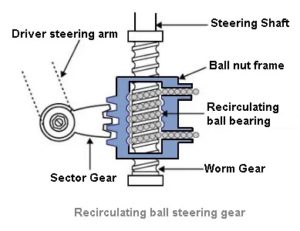
The recirculating ball gear is similar to the worm and ball bearing nut steering gear. These balls have half nut and a transfer tube. When the cam or worm rotates the ball passes from one side of the nut to the transfer tube to the opposite side. As the nut cannot turn, the movement of the balls with the track of cam carries the nut allow it and rotate the rocket shaft.
2. Rack and Pinion Steering Gear
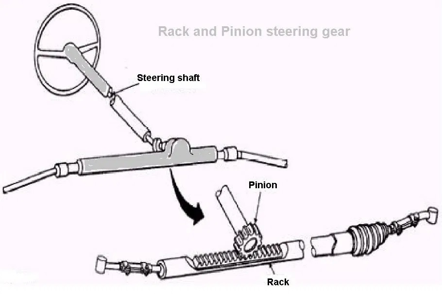
The rack and pinion steering gear, a pinion is mounted on the end of the steering shaft. This engages the rack with the rack having a ball joint at each end for allowing the rise and fall of the wheels.
Roads connect the ball joint to stub excels. Rotary movement of a steering wheel and pinion moves the rack sideways and this movement of rack converted into wheels.
3. Worm and Sector Steering Gear
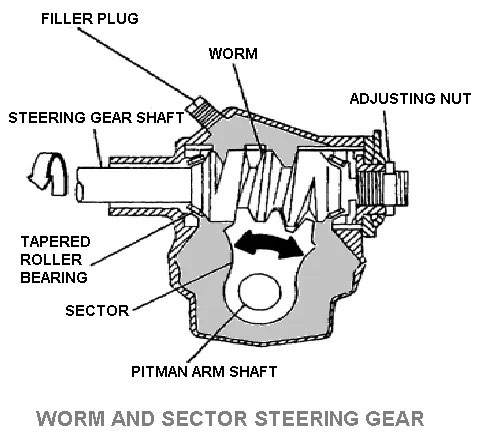
The worm on the end of the steering shaft meshes with a sector mounted on the sector shaft. The worm is rotated by rotation of steering wheel and the sector turns a sector shaft and the motion is transmitted to the wheel via linkage.
The sector shaft is also known as pitman arm shaft, pitman shaft, roller shaft, steering arm shaft, and cross shaft.
4. Worm and roller steering Gear
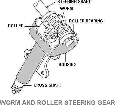
The two-toothed roller is fastened to the sector or roller shaft for meshes with the threads of the worm gear or shaft at the end of the steering shaft or tube.
The worm shaft turned the roller to move in an arc to rotate the roller shaft and the pin connect it to the shaft and the roller is mounted on the ball bearing.
This worm shaft is mounted on bearing to resist both radial and end thrust and it is widely used in American passenger cars.
5. Worm and Ball Bearing Nut Steering Gear
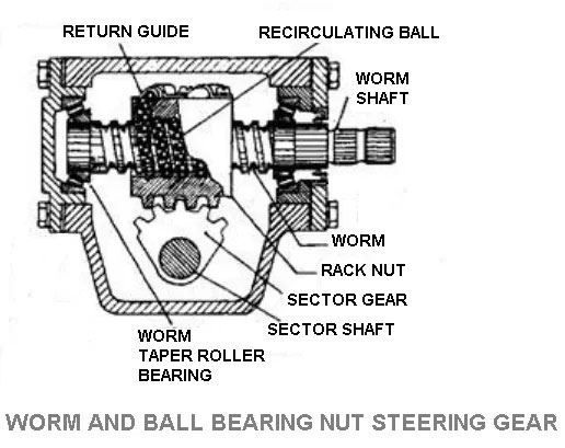
There is a ball nut mounted on the worm of the steering shaft. Worm and nut have mating spiral grooves and the steel balls circulate to provide the frictionless drive between worm and nut.
There are two sets of balls are used and each set is operating independently. The ball return guide is attached to the outer surface of the nut. When the steering shaft is turned to the left or right the ball nut is move up and down by balls in which roll between the worm and nut.
The sector gear is mounted on the sector shaft meshes with the ball nut so it gets motion by ball nut.
6. Cam and Roller Steering Gear
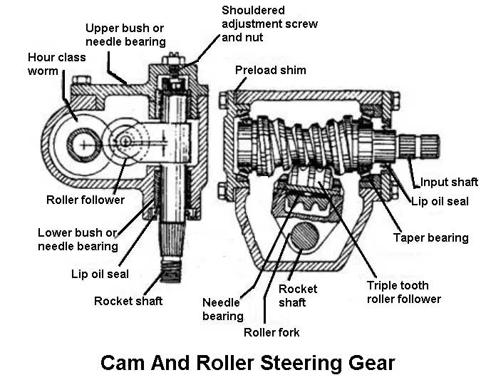
The cam meshes with the roller in cam and roller steering gear. With the rotating cam, the roller is compelled to follow the cam in doing to causes the rocker shaft to rotate and moving the drop arm.
This is designed to mesh with the arc made with roller for maintaining a constant depth of mesh and distributing equally the load and wear on the mating parts.
7. Cam and Peg Steering Gear
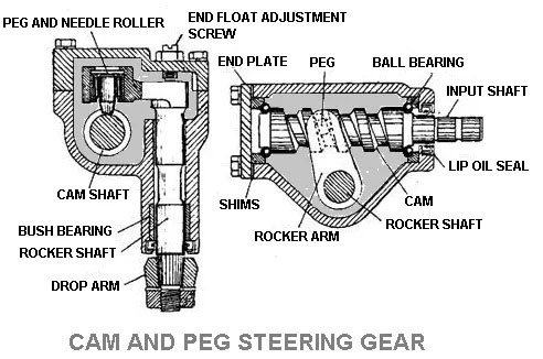
The cam and peg steering attached to rocker arm and is tapered peg and it engages in the cam. When the cam is rotated the peg moves with the groove cause the rocker shaft to rotate.
8. Cam and Double Lever Steering Gear
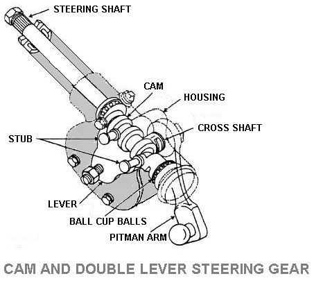
The cam and double lever steering gear is a special worm called a cam and it is replacing the worm used in two types of worm and sector steering gear and worm and roller steering gear.
Cam has a cylindrical shape and the actuating part is grooved of variable pitch and it became narrow at the center than the end. It provides non-reversibility in the center part of the cam and with this the steering takes place.
Twin levers are mounted on the cross shaft and located so the stubs engage the cam from the side. After turning off the cam, the stubs are moved with the cam groove for the lever to swing via arc and this turning the cross shaft.
This is the information about the Steering System pump.
🔔We hope this information will help you. For more new information click on the notification button and get regular updates from Unbox Factory.
Now if you find this information helpful, share it with your friends, family, and colleagues.
If you like this post, let us know by comment below, if you want to add-on information about this topic, comment the information. We will consider the information if it is relevant.
Thank you for reading.


